First of all, we need to understand what is meant by jitter. In most simplistic language, jitter is the uncertainty of a clock source in production of clock edges. For example, if we say that there is a 100 MHz clock source. Ideally, it should produce a clock edge at 0 ns, 10 ns, 20 ns... So, if we say that there was a clock edge at time t = 30 ns, we should get the next clock edge at t = 40 ns. But this is hardly so; due to the uncertainty of getting a clock edge, we might get the next edge between 39.9 ns to 40.1 ns. So, we say that 0.1 ns is the jitter in the period of the clock. In reality, the definition of jitter is more complex. But, for our scope, this understanding is sufficient.
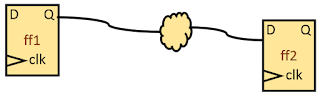
Let us consider a simple timing path from a positive edge-triggered flip-flop to a positive edge-triggered flip-flop.

Now, let us come to our discussion. First, let us discuss the effect of clock jitter on setup slack.
Effect of clock jitter on setup slack for single cycle paths: From our knowledge of STA basics, setup check formed, in this case, will be from edge 1 -> edge 3. Now, if we know that edge 1 arrived at 20 ns, then edge 3 may arrive at any time (20 ns + CLOCK_PERIOD + jitter) and (20 ns + CLOCK_PERIOD - jitter). So, to cover worst case timing scenario, we need to time as per (20 ns + CLOCK_PERIOD - jitter). So, effectively, we will get (CLOCK_PERIOD - jitter) as effective clock period.
 In other words, jitter in clock period makes the setup timing more tight. Or it decreases setup slack for single cycle timing paths.
Effect of clock jitter on hold slack for single cycle paths: Going on the same grounds as setup slack, hold check will be from edge 1 -> edge 1 only. And we know with certainty that edge 1 will leave the source at 20 ns only. So, hold slack should not get bothered by the amount of jitter present at the clock source for single cycle timing paths.
Now, you understand the basics of how jitter affects setup and hold slacks. We can state as below:
If the check being formed involves two different edges of same polarity (for instance, different rising edges), then, jitter in clock period will affect setup slack. Otherwise, it will not.
Now, can you guess the effect of jitter on setup and hold slacks for zero cycle timing paths?
Also, what will be the amount of pessimism needed to be taken into account for setup and hold slacks' calculations if the timing path is a multi-cycle path taking 2 cycles for setup and zero cycle for hold?
Also read:


