Showing posts with label Design basics. Show all posts

How clock gating reduces power dissipation

As discussed in clock gating - basics, enable signal coming in data path is transferred into clock path in order to save dynamic power. But the question is exactly how is this power saved. In this post, we will discuss the same. 


A flip-flop implemented as a standard cell mostly has two internal inverters to generate clk' and clk_delay signals. So, even if the flip-flop input is kept constant, there is still toggling of data at these inverters, thereby dissipating dynamic power. In addition to this, there is internal power dissipation inside flip-flop due to charging and discharging of transistors' gates repetitively because of clock toggling, but this component is not a significant factor compared to dynamic power of inverters. Figure 2 below shows the internal structure of flip-flop, which has two latches in master-slave configuration and two inverters in clock path.

Figure 2: Flip-flop internal structure

Every clock cycle, these two inverters toggle regardless of flip-flop output toggling. However, implementation of clock gating will prohibit the toggling of these inverters when data is not toggling. Let us assume that a latch-based ICG is inserted. Thus, a mux in data path is replaced by an ICG in clock path. But there is a difference here. If there are, say 1000, flip-flops with same enable signal, there will be a common ICG inserted for these. Thus, instead of now 2000 inverters (inside 1000 flops) toggling when flip-flop output will be constant, we have only 2 inverters inside ICG consuming dynamic power. This is how dynamic power is saved. However, if only 1 flop had been clock gated in this manner, there would not have been any dynamic power saving, instead we have an ICG instead of a latch, it may result in overall loss in terms of area and power.

Whether there is any net saving is governed by how many flips-flops have been clock gated using a single ICG.

Also, as discussed, many muxes in data path with same enable are replaced by an ICG in clock path. Thus, there are advantages in terms of area and leakage power too, in addition to dynamic power.

Design query : How can we construct a 101 non overlapping counter using only combinational circuit for 32 bit input for example on considering 10101001 i want an output as 1 since there is only 1 101 non overlapping sequence

Solution: The design in question is a combinatorial design with 32-bit input (given) and a 4-bit output as shown in figure 1 below. How the output is 4-bit is a bit tricky. For this, we have to understand the problem. We have to count the number of non-overlapping "101" sequences in 32-bit input. Thus, "10101" counts as only a single occurrence, and "101101" counts as two occurrences. So, the maximum number of such patterns will occur when "101101" is repeated, which comes out to be 10 in a 32-bit number. 10 can be represented by a 4-bit number.

Figure 1: Design representation
One of the solutions, of course is to make a truth-table and then find a solution using logic equation solving. But the number of combinations possible here is huge and practically impossible to find a solution. So, we need to follow a modular approach here.

We can divide the problem into two parts, detecting the required pattern and then counting how many patterns actually were detected. We are introducing an intermediate 32-bit output, each bit (Nth bit) detecting if the pattern was found with Nth bit of input as the middle symbol of pattern. To detect non-overlapping "101" pattern, we need to look into 2 bits on each side, thereby making a combinational logic comprising of 7 bits. There will be special cases for terminal bits (here bit-0, bit-1, bit-30 and bit-31) where we know that there are less than 2 bits on one side. So, we need to have special logic for these bits.

The overall combinational logic will look like as shown in figure below. Int-N (Nth bit of intermediate output) is a resultant of (Bit-N-3 to Bit-N+3). The number of 1's in the intermediate output will tell how many patterns were detected, which, as discussed earlier, will be maximum 10.
Figure 2: Block diagram representation of design
Let us, now, proceed for a generic logic for Nth intermediate output. As discussed, Nth output (On) depends upon 7 bits, 3 bits on the up and 3 on down. The Nth bit of output will show "1"only for following cases: X1101XX & 00101XX. As 10101XX will be detected as "1" for N+2 bit of output. If we denote the variables involved as G,F,E,D,C,A, then the output expression becomes

On = FED'C + G'F'ED'C
On = ED'C (F+G')

 For bit 31, the upper two bits do not exist. 101XX is the expression for getting output as 1. Thus, the equation, on a similar note, can be expressed as:
O31 = ED'C

For bit 30, the expression comes out to be X101XX. So, O30 also has same logic as O31.

For O1 and O0, we get the same expression as we get for On. The logic diagram for obtaining intermediate outputs is shown in figure 3 below:

Figure 3: Circuit with logic for intermediate output


Now, we have got the intermediate outputs showing which bits have the specified pattern detected. The number of "1"in the final output is our final answer. So, we need a special circuit to count the number of 1's combinationally in a bus as shown in figure 3 above. "Combinationally count number of 1's in a bus" explains how we can do this.

This post is in response to a query posted on our "post your query" page. In case you want to have an answer to your query, you can post a comment. We will try our best to answer.

Design query :: Combinationally count number of 1's in a 32-bit bus

Solution: The design in question is a combinational design with 32-bit input and 6-bit output as there can be maximum 32 1's and 32 stands "100000" in binary. Making a truth-table or K-map for this problem is not practical, so we have to take a modular approach. Let us divide the problem into detecting number of 1's among 4 bits and then adding the resulting numbers together providing the total count.

Let us first create a truth-table converting the number of 1's in a 4-bit stream into a 2-bit number. The resulting truth table is shown in figure 1.

Figure 1: Truth table for 4-bit count 1's circuit

Solving the above for O2, O1 and O0 using K-maps, we get the expressions as shown in figures 2, 3 and 4 below.

Figure 2: Expression for O2

Figure 3: Expression for O1


Figure 4: Expression for O0

Thus, we have 8 instances, each counting the number of ones pertaining to respective 4 bits. The next thing we need is to add these 8 three-bit numbers to obtain the resultant total number of 1's in the 32-bit number we got. For this, we can again follow modular approach to add two numbers at a time until we are left with a single number. The block diagram of the complete solution is shown below in figure 5.

Figure 5: Complete block diagram of counting number of 1's


Half-handshake synchronization scheme

Synchronization questions is one of the favorites among VLSI job interviewers. This is because they check not just the general intellectual abilities of the potential candidate but also the very specific professional knowledge which is usually acquired only by experience. When it comes to synchronization there are plenty of schemes. During the emerging interview it often comes to the "ultimate" decision - the synchronizer, which is tolerable to any source-destination conditions (relative frequencies, duration of signals, etc). The expected answer is very well known full-handshake scheme. It is definitely the "ultimate" solution. But its extra-generic nature comes at a cost of very long processing cycle (6 source + 6 destination cycles).

Less known is half hand-shake synchronization scheme which differs from full hand-shake scheme by that it utilizes signals toggling rather than level as an indication to transfer synchronization information from side to side.


At source and destination sides it is toggling (0 to 1 signal change or vice versa) of the synchronized valid signal or ack signal, which becomes an indication the synchronized output may be issued and/or the state changed. Toggled signal may be achieved by comparison (XOR) of the next and current signal value. The current signal value need to be latched at each processing cycle.

Half-handshake scheme provides 2 times better processing cycle than full hand-shake because it consists of only synchronization-acknowledge cycle rather than of synchronization-acknowledge-synchronization de-assertion-acknowledge de-assertion.

How can we generate a pulse for every edge of the incoming pulse

It is a very common requirement to detect either positive edge, negative edge or both edges of a signal. And the circuit that can detect and generate a single cycle pulse is quite simple. In this post, we will discuss how we can detect positive edge, negative edge and both edges of a signal.

  • Detect positive edge of a signal: Positive edge of a signal means that the current state of the signal is "1" and previous state is "0". And a pulse signal means that the output of the circuit is "1" for one cycle. So, we need a circuit which generates "1" as output when present state is "1" and previous state is "0". It generates "0" as output otherwise.
Thus, output = D(n-2)' & D(n-1)
The required implementation is shown in figure 1 below:
Figure 1: Detection of positive edge of signal

  • Detect negative edge of a signal: Negative edge of signal means that the current state of the signal is "0" and previous state is "0". So, we need a circuit which generates "1" as output when present state is "0" and previous state is "1". It generates "0" as output otherwise. 
Thus, Neg_edge_detect = D(n-2) & D(n-1)'
 The required implementation is shown in figure 2 below:
Figure 2: Detection of negative edge of signal


  • Detecting both positive and negative edges of the signal: Simply doing an "OR" operation of Pos_edge_detect and Neg_edge_detect signal will produce an output which is a single cycle pulse for any of the edge of incoming signal. The requirement for consecutive edges of incoming signal is to be at least 2 cycles apart otherwise, the output will not be pulse, but will be a continuous signal.
Any_edge_detect = Pos_edge_detect + Neg_edge_detect
The required implementation is shown in figure 3 below:

Figure 3: Detection of both positive and negative edges of signal

The technique we discussed here delays the output by two cycles. Can you think of any other way to detect the edges of a signal which is more efficient?


Interview questions related to clock jitter and duty cycle variations

Below we list few of our posts related to clock jitter and duty cycle variation. Happy learning.


  • Clock jitter: Disusses the definition and types of clock jitter.
  • Duty cycle of clock: Discusses the definition of duty cycle and how it impacts timing slack of timing paths.
  • Duty cycle variation: Discusses in detail basics of duty cycle variation and its timing implications.

Our purpose is to make this page a single destination for any questions related to clock jitter and duty cycle variation. Please feel free to ask any question related to clock jitter and duty cycle variations.

Duty cycle care-abouts for clock paths in reset assertion

In the post Asynchronous reset assertion timing scenarios, we discussed how we may need to time the assertion of asynchronous reset as well. In this post, we will talk about how important it is to talk about the duty cycle aspect as well. We will use the same example as we did in our previous post to help make a better connection.

In the figure below (discussed in Asynchronous reset assertion timing scenarios), Q0 goes from 0 ->1 and 1 -> 0 in the same cycle, thereby providing a very diminished high pulse, or very diminished low pulse to BIT_1 flip-flop depending upon the delay in reset path of BIT_0 flip-flop. This can result in violation of minimum pulse width requirement of BIT_1. We will discuss this in some detail in this post.

Let us talk only about clock edge number 4. Q0 goes 1 and BIT_1 receives it as positive edge of clock, thereby changing state too. The delay till BIT_1 receiving positive edge of clock is given as

POS_CK_AT_BIT_1 = (Latency of BIT_0) + (CLK->Q of BIT_0) + (BIT_0/Q -> BIT_1/CK)

Now, both Q0 and Q1 go 1, thereby causing the output of NAND gate going "0", which asserts the reset of both BIT_0 and BIT_1. BIT_1 now receives negative edge of clock, whose delay is

NEG_CK_AT_BIT_1 = (Latency of BIT_0) + (CLK->Q of BIT_0) + NAND_DELAY + (R -> Q of BIT_0) +   (BIT_0/Q -> BIT_1/CK)

The width of high pulse that the flip-flop receives is equal to the difference between above two values:
HIGH_PULSE_WIDTH_AT_BIT_1 = NAND_DELAY + (R -> Q of BIT_0)

And low pulse is equal to 
LOW_PULSE_WIDTH_AT_BIT_1 = CLK_PERIOD - HIGH_PULSE_WIDTH_AT_BIT_1

Now, depending upon the combinational delays mentioned as well as CLK_PERIOD, BIT_1 may receive a pulse (either high or low) with width less than what is permissible for its proper functionality. Thus, there will be a pulse width violation.

Looking at the equations for high and low pulse widths, it seems more probable to have high pulse width violating for BIT_1, unless either clock period is very less or buffering is there in reset path of BIT_0. We will need to increase buffering to reset pin of BIT_0 to increase width of high pulse and vice-versa.

The discussion we just had is applicable to any design in particular with reset controlling a signal driving another flip-flop's CK pin. However, one may argue following about this particular circuit:

This particular circuit is resistant to high pulse width violation, but may have low pulse width violations.

Can you argue in favor/against this statement? What is the reason for one making this statement. (Hint: Answer lies in the sequence of events causing CK to BIT_1 to go high and then go low).

Also read:


Asynchronous reset assertion timing scenarios

We have always heard that for asynchronous resets, only de-assertion needs to be timed. This is true for most of the designs as the guidelines followed for implementation of asynchronous resets. However, there may be a  scenario wherein we may need to consider reset assertion as well for our timing checks. In this post, we will try to put some light on it.

In our post "recovery and removal checks", we have elaborated following for asynchronous resets:

* Reset assertion "combinationally" causes the output to go 0; i.e., assertion of reset does not wait for edge of the clock to alter the state of flip-flop

* Reset de-assertion waits for clock edge to propagate the value at "input" to "output". There are checks corresponding to de-assertion of reset with respect to clock known as "recovery" and "removal" checks.

Thus, we see that "recovery" and "removal" checks are defined only for de-assertion of asynchronous reset. So, one must think that there is no timing requirement for reset assertion. This is true in the sense that there is no requirement for reset assertion at the flip-flop that is receiving reset. And overall no timing requirement for a carefully implemented design. But some-times, there may be a corner-case scenario requiring the combinational path throuhg "reset -> output" to be timed. We will discuss some cases to elaborate our statement.

CASE 1: The output of flip-flop goes to another flip-flop, which itself is getting reset at the same time.
Here, since, the output in fanout is itself in reset state, it will not be sampling the output. Hence, there is no need to time the assertion of reset.


CASE 2: The output of flip-flop goes to an asynchronous domain or to a synchronizer which is not, itself, in reset. Here, the asynchronous domain flip-flop is expected to be a synchronizer in most of the cases. So, there does not arise a need for meeting timing.

CASE 3: The output of flip-flop goes to a flip-flop which is working on a synchronous clock and is expecting synchronous data. In this case, we will have to meet timing through the R -> Q of the source flip-flop and getting captured at the destination. We need to keep in mind that reset synchronizer also transfers through R -> Q for reset assertion. So, this case cannot be valid for global asynchronous reset assertion. For instance, let us consider below as a valid scenario.
For below case, we have to meet reset assertion timing from
ASYNC_RESET_SOURCE -> REG_B/R -> REG_B/Q -> REG_C/R -> REG_C/Q -> REG_D/D

Since, reset source is working on asynchronous clock, this is a design violation to get it captured on a flip-flop which is running functionally and expecting synchronous data.

Thus, there may not be any scenario to time asynchronous reset assertion globally. However, the state machines may locally utilize asynchronous reset assertion to get things done. For instance, you must have gone through a common problem known as "conversion of asynchronous counter to decade counter", wherein asynchronous reset pin is utilized to reset the count whenever count reaches 10. We will simplify it as "conversion of 2-bit asynchronous counter to modulo-3 counter" to serve our purpose.

Consider following design of 2-bit asynchronous counter. We have shown two flip-flops to register the output of this counter for illustration purposes and to make the understanding more clear. Flip-flop "BIT_1" gets the output of "BIT_0" as clock. All other flip-flops get CLK as clock. Whenever output of both "BIT_1" and "BIT_0" goes 1, the reset of both flops will cause output to go "00" in the same cycle. This is expected to reach the registers by next clock cycle so that it can be captured properly. The intermediate state "11" is not captured at the next stage as understood by basics of state machines.


We get following timing equations to be met in a single cycle (minus setup time and skews etc.).
BIT_1/CK -> BIT_1/Q -> BIT_1/R -> BIT_1/Q -> REG_1/D
BIT_1/CK -> BIT_1/Q -> BIT_0/R -> BIT_0/Q -> REG_0/D
BIT_0/CK -> BIT_0/Q -> BIT_1/R -> BIT_1/Q -> REG_1/D
BIT_0/CK -> BIT_0/Q -> BIT_0/R -> BIT_0/Q -> REG_0/D

Thus, this is an example of a scenario wherein we need timing for assertion of reset as well. It is captured at the next flip-flops running combinationally through the flip-flops' "Q" pin. Can you deduce the timing paths to be timed for the original case of "asynchronous counter as a decade counter" as well.

Another possible care-about of asynchronous reset assertion may be degradation of duty cycle, if the output is used as a clock such as highlighted path, where Q0 is being consumed as clock for "BIT_1" flip-flop. This can cause the minimum pulse width requirement to be violated for "BIT_1" flip-flop. This perspective of reset assertion is discussed here.

Also read:


Can we use discrete latches and AND/OR gates instead of ICG?

In the post, Integated Clock Gating Cell, we discussed that an ICG has a negative level-sensitive latch preceding an AND gate in order to relax hold timing for clock gating check. And we discussed that it gives benefits for area, power and timing. Let us discuss how area, power and timing are saved. We will discuss only for the case of AND gate, the same will follow for OR gate.

1. Architectural benefits - simplicity in clock handling: By introducing ICGs in place of discrete gates, you dont have to worry about the launch edge of the signal while writing RTL (for details, see here). One can always launch the signal from positive edge-triggered flip-flop for timing and architectural simplicity without worrying about possibility of glitch in clock path due to wrong polarity flip-flop launching enable signal.

2. Benefits in area and power: Having custom module allows for better utilization of resources inside the custom ICG module; hence, it is expected to have lesser power than a latch and an AND gate combined.

3. Benefits in timing: Having the path from latch -> AND inside ICG saves us from having to meet these paths individually, which could take a lot of effort with discrete latch and AND gate. Also, it allows for latch to have almost full time borrow, thereby making almost a full cycle path from a positive edge-triggered flip-flop to ICG.

Also read


Design problem: Clock gating for a shift register

Problem: There is an 4-bit shift register with parallel read and write capability as shown in the diagram. We need to find out an opportunity to clock gate the module.

 Mode selection bits ("S1" and "S0") are controlling the operation of this shift register with following settings:

Solution: From the basics of clock gating, we know that if the stae of a flip-flop is not chaging, there lies an opportunity to gate its clock. Observing the table, we see that state of all flip-flops does not change when "S1,S0" are either "00" or "11". So, when mode selection bits are corresponding to these values, we can gate the clock to this shift register. Or, we can say that clock to the module should reach only when (S1 xor S0) is equal to 1.


Can you relate the timing of S1 and S0? Should they be coming from positive edge-triggered flip-flop or negative edge-triggered flip-flop? Clock gating checks explains the timing of clock gating signals with respect to clock.

Also read:


What is the difference between a normal buffer and clock buffer?

A buffer is an element which produces an output signal, which is of the same value as the input signal. We can also refer a buffer as a repeater which repeats the signal it is receiving, just as there are repeaters in telephone signal transmission lines. You must have noticed that we have two kinds of buffers (or any logic gate) available in standard cell libraries as:

  • Clock buffer: The clock buffers are designed specifically to have specific properties that are supposed to be good for clock distribution networks (clock trees). The specific properties that are required in an ideal clock tree buffer are given as below. However, it is not possible to attain these ideal properties for every buffer at every technology node. It may be only possible to get close to these properties.
    • Equal rise and fall times
    • Less delays
    • Less delay variations with PVT and OCV
  • Normal buffer/data buffer: For a data buffer, the above properties are usually less desired
Usually, we can say that following differences may exist between a clock buffer and a normal buffer:
  • In SoCs, clock routing is done in higher metal layers as compared to signal routing. So, to provide easier access to clock pins from these layers, clock buffers may have pins in higher metal layers. That is, vias are provided in standard cell itself instead of necessitating on having in clock distribution network. For a data buffer, the pins are expected to be in lower layers only.
  • Clock buffers are balanced. In other words, rise and fall times of clock buffers are nearly equal. The reason behind this is that if the clock buffers are not balanced, there will be duty cycle distortion in the clock tree, which can lead to pulse width violations as discussed in minimum pulse width violation example. On the other hand, data buffers can compromise with either of rise/fall times. In other words, they dont need to have PMOS/NMOS size to be 2:1; and hence, can be of smaller size as compared to clock buffers.
  • Due to above reason, clock buffers consume more power as compared to normal buffers.
  • Generally, you will find clock buffers with higher drive strength as compared to normal buffers. So that a clock buffer can drive long nets and can have higher fanouts. This helps clock buffers, and hence, clock trees to have less overall delays.

What is meant by drive strength of a standard cell

As we know that cell delay is a function of output load capacitance. The most simplistic equivalent circuit of a logic gate driving an output can be assumed as given in figure 1:


The purpose of logic gate is to propagate the effect of logic value available at its input to the output. Based upon whether '0' or '1' is to be propagated to the output. The corresponding is achieved by charging and discharging of the output load capacitance. Propagating a logic '0' will mean discharging of the load capacitance, and vice-versa. Drive strength of the logic gate is the its relative capability to charge/discharge the capacitance present at its output. Now, the time constant, and hence, delay of the circuit is "RC".
So, for a cell with higher drive strength, corresponding "R" is lesser than the one with lower drive strength. So that for same load capacitance "C", delay is lower for a cell with higher drive strength as it can charge the capacitance in lesser time.

How drive strength varies with size of a cell: Let us talk in terms of MOSFETs, although this is valid in terms of every device in general. We know that for a given technology standard cell library, length of all transistors is kept constant. For instance, 90 nm technology will have gate length of all transistors as ~90 nm. And channel resistance of the MOSFET is inversely proportional to "W/L" of the transistor. So, a simple way to decrease channel resistance is to increase "W" of the transistor. So, a transistor with more area will have lesser resistance. Or we can say that a logic gate with bigger transistors will have more drive strength.

What is unit drive strength: In a standard cell library, we generally see cells labelled as "1X", "2X" and so on. But what is meant by the number that you see with drive strength? In general, the lowest size logic gate is labelled as unit drive strength. The drive strength numbers of other cells are laelled relative to unit drive strength cell.

Read next: How delay of a cell changes with drive strength

Also read:

Why setup is checked on next edge and hold on same edge? Setup and hold – the state machines essentials

Hi friends, in the post State machines – a practical perspective, we learnt about state machines. We also discussed different aspects of a state machine with the help of an example and the need of setup and hold checks to be taken care of. In this post, we will be discussing the state machine with a pinch of setup and hold and try to build a better understanding regarding these. For recapitalization, see figure 1. Each clock edge in a digital state machine represents a state. At each clock edge, all the registers in the design update their value based upon the data available at their input which is based upon the value computed on the basis of values launched by some other registers at previous clock edge. In simplest of words, state 3 is dependent upon state 2, which, in turn, is dependent upon state 1 and so on.

Each state of a state machine can be represented by a clock pulse
Figure 1: State machine representation of a clock pulse

All digital systems are synchronous systems (state machines) that require all the elements of the state machine to be in harmony. For instance, let us say, a state machine has 100 registers. All these registers need to be updated at the same time and need synchronized inputs so as to have only valid states in the state machines. For digital synchronous state machines, all the registers are synchronized by a clock signal. This is ensured with the help of setup and hold checks. But why do we need to apply setup and hold checks, is the question still unanswered.

Why setup and hold? We often encounter people saying that meeting the setup and hold requirements of a design is critical for silicon functionality. But have you ever thought why it is so? As we now know from our previous post, for a design consisting of only positive edge-triggered registers, each positive clock edge corresponds to a state and the state of the machine is updated at every clock edge since all the flip-flops capture data. In other words, the state of the machine is a function of the values of the registers at a particular clock cycle. For proper state machine functioning, the values launched from one register at one clock edge should be available at the input of the capturing flop before next clock edge arrives and should be available only after the present clock edge has passed (will become clear later on). This is necessary in order that the next state of the state machine is a valid state. If this does not happen, the state of the machine will not be what is desired. It may also happen that the state machine goes altogether into an invalid state leading to undesired results. And this is the reason setup is checked on the next edge and hold on same edge as discussed below.
Let us assume a hypothetical state machine consisting of three registers and some logic gates as shown in figure 2 below. If we assume the initial outputs of REG1 and REG2 to be 1 and 0 respectively, then the possible states can only be 100 or 010.

The shown state machine consists of three registers
Figure 2: A state machine with three registers and some logic

The state transition table for this state machine is as shown in figure 2. As is shown, there are only two valid states (100 and 010) provided the initial state of REG1 and REG2 is different (10 or 01). The state of REG3 is supposed to remain always ‘0’ as the REG1 and REG2 are supposed to always have different values at a time (given initial condition is also this).
State diagram of state machine shown in figure 2
Figure 3: State diagram of state machine shown in figure 2

The states with respect to clock waveform are as shown in figure 4 below. As is expected, each clock edge corresponds to one of the two states.

Figure 4: Clock waveforms showing different states of state machine

Now, the state of register 2 at a particular state (clock edge) depends upon state of register 1 at the previous clock edge. Let us assume register 2 is getting delayed clock with respect to register 1. In other words, there is considerable positive skew between the two registers. In this case, as shown in figure 5 below, there is a good chance that the data launched from register 1 is captured at register 2 at the same edge and not the next clock edge. Due to this, both register 1 and 2 will have same value at a particular clock cycle and the machine will run into invalid state. The data getting captured at the same edge as the launch flop is termed as hold violation (unless it is architecturally intended, the discussion of this is outside the scope of this topic).
The hold violation results due to data being captured on the same edge as it is launched on
Figure 5: Hold violation resulting in state machine going to invalid state
Similarly, for the proper functioning of the state machine, the data launched at one edge should get captured at the next edge. This is what is termed as setup check. Thus, setup check is formed on next edge only. The failure in happening so is termed as a setup violation. Similarly, the data launched at one edge should not be captured on the same edge. Thus, hold check represents this situation and ensures that the data launched on one edge is not captured on the same edge.

Based upon development of our understanding in this post, setup and hold can be defined as:

Setup check: Setup check refers to the condition in which data launched at one clock edge should get captured at the next clock edge so that the state machine functionality is preserved and the state machine transitions smoothly from one state to the next. The failure in happening so is termed as setup violation and the state machine might transition to an invalid state.


Hold check: Hold check refers to the condition in which data launched at one clock edge should not get captured at the same clock edge so that present state of the state machine does not get corrupt. The failure in happening so is termed as hold violation and the state machine might transition to an invalid state.

Clock multiplexer for glitch-free clock switching

In the post clock switching and clock gating checks, we discussed how important it is to have a glitch free clock. Also, in clock gating checks at a multiplexer, we discussed the conditions wherein a normal multiplexer can be used to propagate a clock without any glitches. 


In this post, we will discuss about multiplexer circuit for clock switching which can safely switch clocks without the probability of any glitches under most of the scenarios, hence, also called glitch-less multiplexer.


Definition of clock multiplexer: Let us first define a clock multiplexer "A clock multiplexer is a circuit that can switch the system from one clock to another while the chip is running. The two frequencies may be related to each other, or may to totally unrelated". A clock multiplexer switches the clock without any glitches as the glitch in clock will be hazardous for the system. Hence, a clock multiplexer is also known as a glitchless multiplexer.

Clock multiplexer for switching between two synchronous clocks:


Clock multiplexer for switching between two asynchronous clocks:


Reference: A very detailed and good explanation is provided at below link. I recommend to go through this for complete understanding of the process.
http://www.eetimes.com/document.asp?doc_id=1202359


Also read:

8x1 multiplexer using 4x1 multiplexer

An 8x1 mux can be implemented using two 4x1 muxes and one 2x1 mux. 4 of the inputs can first be decoded using each 4-input mux using two least significant select lines (S0 and S1). The output of the two 4x1 muxes can be further multiplexed with the help of MSB of select lines at further stage. The implementation of 8x1 using 4x1 and 2x1 muxes is shown in figure 1 below:


XNOR gate using NAND

As we know, the logical equation of a 2-input XNOR gate is given as below:
                      Y = A (xnor) B = (A' B '   +    A B)
Let us take an approach where we consider and A' as different variables for now (optimizations related to this, if any, will consider later). Thus, the logic equation, now, becomes:
                       Y = (CD    +    A B)           -----   (i)
     where
                      C = A'     and      D = B'
De-Morgan's law states that
                                m + n = (m'n')'

Taking this into account,
                     Y = ((CD)'(AB)')' = ((A' B')'  (A B)')'
Thus, Y is equal to ((A' nand B') nand (A nand B)). No further optimizations to the logic seem possible to this logic. Figure 1 below shows the implementation of XOR gate using 2-input NAND gates.
A 2 -input XOR gate implementation using NAND, XOR gate using NAND
Figure 1: 2-input XNOR gate implementation using NAND gates

2x1 mux using NAND gates

As we know, the logical equation of a 2-input mux is given as below:
                      Y = (s' A   +    s B)
Where s is the select of the multiplexer.
De-Morgan's law states that
                                m + n = (m'n')'

Taking this into account, here m = s'A  and  n = sB
                     Y = ((s'A)'(sB)')' = ((s' A)'  (s B)')'
Thus, Y is equal to ((s' nand A) nand (s nand B)). No further optimizations seem possible to this logic. Figure 1 below shows the implementation of 2:1 mux using 2-input NAND gates.
Figure 1: 2:1 Mux using NAND gates

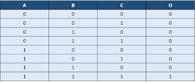
3-input AND gate using 4:1 mux

As we know, a AND gate's output goes '1' when all its inputs are '1', otherwise it is '0'. The truth table for a 3-input AND gate is shown below in figure 1, where A, B and C are the three inputs and O is the output.
                                      O = A (and) B (and) C
Truth table for 3-input AND gate


A 4:1 mux has 2 select lines. We can connect A and B to each of the select lines. The output will, then, be a function of the third input C. Now, if we sub-partition the truth table for distinct values of A and B, we observe
When A = 0 and B = 0, O = 0 => Connect D0 pin of mux to '0'
When A = 0 and B = 1, O = 0 => Connect D1 pin of mux to '0'
When A = 1 and B = 0, O = 0 => Connect D2 pin of mux to '0'
When A = 1 and B = 1, O = C => Connect D3 pin of mux to C
The implementation of 3-input AND gate, based upon our discussion so far, is as shown in figure 2 below:


Also read:

3-input XOR gate using 2-input XOR gates


A 3-input XOR gate can be implemented using 2-input XOR gates by cascading 2 2-input XOR gates. Two of the three inputs will feed one of the 2-input XOR gates. The output of the first gate will, then, be XORed with the third input to get the final output.

Let us say, we want to XOR three inputs A,B and C to get the output Z. First, XOR A and B together to obtain intermediate output Y. Then XOR Y and C to obtain Z. The schematic representation to obtain 3-input XOR gate by cascading 2-input XOR gates is shown in figure below:

Implementation of 3-input XOR gate using 2-input XOR gates


Why NAND structures are preferred over NOR ones?

Both NAND and NOR are classified as universal gates, but we see that NAND is preferred over NOR in CMOS logic structures. Let us discuss why it is so:


We know that when output is at logic 1, pull up structure for the output stage is on and it provides a path from VDD to output. Similarly, pull down structure provides a path from GND to output when output is logic 0. Pull up and pull down resistances are one of major factor in determining the speed of cell. The inverse of pull up and pull down resistances are called output high drive and output low drive of the cell respectively. In general, cells are designed to have similar drive strength of pull up and pull down structures to have comparable rise and fall time.


NMOS has half the resistance of an equal sized PMOS. let us say resistance of a given sized NMOS is R then resistance of  PMOS of same size will be 2R. In NAND gate, two NMOS are connected in series and two PMOS are connected in parallel. So, pull up and pull down resistances will be:

            Pull up resistance = 2R || 2R = R
            Pull down resistance = R + R = 2R


On the other hand, in a NOR gate, two NMOS are connected in parallel and two PMOS are connected in series. The pull-up and pull-down resistances, now, will be:

            Pull up resistance = 2R + 2R = 4R
            Pull down resistance = R || R = R/2


NAND gate has better ratio of output high drive and output low drive as compared to NOR gate. Hence NAND gate is preferred over NOR.


To use NOR gate as universal gate either pull up or pull down structure has to be resized(decrease the length of PMOS cells or increase length of NMOS cells) to have similar resistance as resistance is directly proportional to length (length of channel here).

Also read: