Showing posts with label binary multiplier. Show all posts

Latency and throughput – the two measures of system performance

Performance of the system is one of the most stringent criteria for its success. While performance increases the desirability among customers, cost is what makes it affordable. This is the reason why system designers aim for maximum performance with available resources such as power and area constraints. There are two related parameters that determine the performance output of a system –

Throughput - Throughput is a measure of the productivity of the system. In electronic/communication systems, throughput refers to rate at which output data is produced. Higher the throughput, more productive is the system. In most of the cases, it is measured as time difference between two consecutive outputs (nth and n+1th). Throughput also refers to the rate at which input data can be applied to system.
Let us discuss with the help of an example:

throughput summary diagram


Above figure depicts the throughput of 3 number adder. Result of input set applied at 1st clock cycle appears at output at 3rd clock cycle and in 4th clock cycle next input set is applied and output comes in 6th clock cycle.  Hence, throughput of above design is ⅓ per clock cycle. As we can see from diagram, first input is applied in first clock cycle and 2nd input is applied in 4th clock cycle. Hence we can also say that throughput is rate at which input data can be applied to system.

Latency- Latency is the time taken by a system to produce output after input is applied. It is a measure of delay response of a design. Higher the latency value, slower is the system. in synchronous designs, it is measured in terms of number of clock cycles. In combinational designs, latency is basically propagation delay of circuit. In non pipelined designs, latency improvement is major area of concern. In more general terms, it is time difference between output and input time.
Latency
Relationship between throughput and latency: Both latency and throughput are inter-related. It is desired to have maximum throughput and minimum latency. Increasing latency and/or throughput might make the system costly. Let us take an example. Consider a park with 3 rides and it takes 5 minutes for a ride.  A child can take sequentially these rides; i.e, ride 1, ride 2 and then ride 3. Firstly, let us assume that only one child at a time is allowed to enter park at a time. While he is taking a ride, no one is allowed to enter the park. Thus, the throughput of the park is 15 minutes per child and latency is 15 minutes. Now, let us assume that while a child has finished taking ride1, another child is allowed to enter park. Thus, in this case, throughput will be 5 minutes per child whereas latency is still 15 minutes. Thus, we have increased the throughput of the system without affecting latency and at the same cost.

2 bit Binary multiplier


Binary multiplication process: A Binary Multiplier is a digital circuit used in digital electronics to multiply two binary numbers and provide the result as output. The method used to multiply two binary numbers is similar to the method taught to school children for multiplying decimal numbers which is based on calculating partial product, shifting them and adding them together. Similar approach is used to multiply two binary numbers. Long multiplicand is multiplied by 0 or 1 which is much easier than decimal multiplication as product by 0 or 1 is 0 or same number respectively. Figure 1 below shows the block diagram of a 2-bit binary multiplier. The two numbers A1A0 and B1B0 are multiplied together to produce a 4-bit output P3P2P1P0. (The maximum product term can be 3 * 3 = 9, which is 1001, a 4-bit number). 
2-bit Binary multiplier block diagram, 2 bit by 2 bit multiplier, 2 bit multiplier
Figure 1: 2-bit Binary Multiplier Block Diagram
Let us take an example of multiplying two binary numbers as follows. The process is similar to multiplying two decimal numbers, with a difference that the resulting numbers are all binary.

       110 = 6
X     011 = 3
-----------------------------
                                                             1 1 0                 ; 110 X 1
                                                          1 1 0 x                 ; 110 X 1
                                                       0 0 0 x x                 ; 110 X 0
 ------------------------------
 1 0 0 1 0 =18


Now, we have seen that multiplying a number with binary ‘0’produces all zeroes, and with ‘1’ reproduces the number. So, multiplying two binary numbers is a straightforward job. It can be implemented without much difficulty using shifters, AND gates and adders.

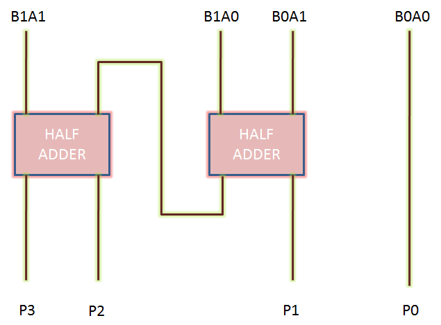
2-bit binary multiplier circuit implementation: Let us implement a two bit binary multiplier. Let the two binary numbers be A1A0 and B1B0. The multiplication table will, then, look as:


                                                          A1         A0
                                           X           B1          B0
-------------------------------------------------------------------
                                                      B0A1       B0A0
                                     B1A1         B1A0             x


-------------------------------------------------------------------
                             P3       P2         P1            P0                                  


Thus, we get the partial products as:
P0 = A0*B0
P1 = A0*B1 xor  A1 * B0                  ; carry generated here goes to next stage
P2 = A1*B1   xor  (A0*B1) * (A1*B0)
P3 = A1*B1   and  (A0*B1) * (A1*B0)


Two bit binary multiplier
Two-bit binary multiplier circuit diagram
Thus, we can see that a 2-bit binary multiplier can be implemented using two half-adders only.

Characteristics of a binary multiplication: As mentioned above, a binary multiplier is used to multiply binary numbers. In general, the characteristics of binary multiplication are as follows:

  • To multiply two binary numbers, AND gates, shifters and adders are required.
  • Product of N*M bit binary numbers in of (N+M) bits.
  •  N*M AND gates are required to generate partial products of two M*N bit binary numbers.
  • Number of adders required =  N+M-2
  • Speed limiting factor here is to sum up  partial products.
Also read: