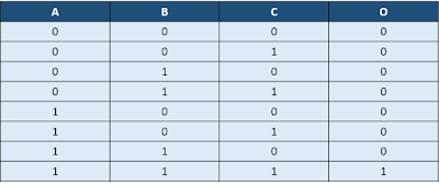
As we know, a AND gate's output goes '1' when all its inputs are '1', otherwise it is '0'. The truth table for a 3-input AND gate is shown below in figure 1, where A, B and C are the three inputs and O is the output.
O = A (and) B (and) C
 |
| Truth table for 3-input AND gate |
A 4:1 mux has 2 select lines. We can connect A and B to each of the select lines. The output will, then, be a function of the third input C. Now, if we sub-partition the truth table for distinct values of A and B, we observe
Also read:
When A = 0 and B = 0, O = 0 => Connect D0 pin of mux to '0'
When A = 0 and B = 1, O = 0 => Connect D1 pin of mux to '0'
When A = 1 and B = 0, O = 0 => Connect D2 pin of mux to '0'
When A = 1 and B = 1, O = C => Connect D3 pin of mux to CThe implementation of 3-input AND gate, based upon our discussion so far, is as shown in figure 2 below:
Also read:

No comments:
Post a Comment
Thanks for your valuable inputs/feedbacks. :-)