Power aware RTL design


With the progress in technology, the designs are moving into deeper sub-micron technology nodes. There is an ever-increasing concern about power dissipation within the SoC. But this should not come at the cost of performance. So, along with less power dissipation, there is need for maximum power efficiency, that is maximum proportion of available power should be used for useful purposes rather than just to keep the device awake. Now the question arises: Whether to start planning from power perspective at the RTL Design level or wait for the problems to be fixed in the backend flow of the design cycle. The answer is former. Efforts are made to achieve maximum power efficiency along all the stages of the design. But the backend flow can only implement the changes at physical level. It cannot fix the micro-architecture which has a significant impact on the dynamic power dissipation within the SoC.


Figure showing Impact of design change on performace
Power aware design is achieved at several levels of abstraction. System design starts from system requirements and specification and goes through design at architecture design, RTL design, gate level design and finally, layout design. At all these stages, techniques are adopted to meet the design power and performance requirements. It has been found that any effort that is made to improve the power efficiency along all the design stages has maximum impact, if it is done at the RTL level. But, the impact is measured most immediately if it is done at the layout level. So, it is very difficult to measure the impact of any architectural change at RTL level. Improvements are needed for power estimation methods at the RTL level. But, it does not mean that backend techniques should not be adopted.

Power aware design is often misunderstood as low power design. But, these are not the same. By low power design, we mean minimizing the power consumption with or without any performance constraint. But by power aware design, is meant the minimizing the power dissipation without any impact on power. Power aware design refers to maximizing some other performance constraint without any significant impact on power efficiency. Achieving maximum performance being constrained to a particular power budget is the aim of power aware design. 

As said earlier, there is an ever increasing demand for low power devices. As these devices run on batteries having limited supply, and the requirement for them is to operate the maximum they can on a single battery. There are long phases of device idle time. In between, the device is active for very small periods of time. And during the active time, high performance is the requirement. One such example is digital energy meters where there is requirement to keep record of the total kWh used. The power may be available in patches, or may be continuously available. There may be long periods when there is no power. Since the power is available, we can afford to have chargeable batteries, but the watts consumed by the controller itself should be very less as compared to the total power consumed so as to minimize the overhead. During the idle periods, device may go to sleep mode so as to save power. As long as power is available, it should wake up immediately. In other words, average power is less but variance in power consumption is very high.  Hence, it requires a provision in RTL to sense incoming signal levels and to change the gears accordingly. There are many techniques adopted for power aware RTL designsuch as performance throttling, judicious module selection, incorporation of power information in RTL, voltage and power islands and power aware design of memories.

Read also:

2 bit Binary multiplier


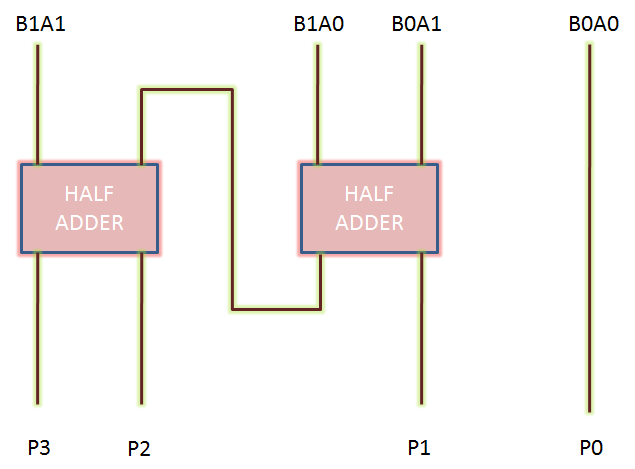
Binary multiplication process: A Binary Multiplier is a digital circuit used in digital electronics to multiply two binary numbers and provide the result as output. The method used to multiply two binary numbers is similar to the method taught to school children for multiplying decimal numbers which is based on calculating partial product, shifting them and adding them together. Similar approach is used to multiply two binary numbers. Long multiplicand is multiplied by 0 or 1 which is much easier than decimal multiplication as product by 0 or 1 is 0 or same number respectively. Figure 1 below shows the block diagram of a 2-bit binary multiplier. The two numbers A1A0 and B1B0 are multiplied together to produce a 4-bit output P3P2P1P0. (The maximum product term can be 3 * 3 = 9, which is 1001, a 4-bit number). 
2-bit Binary multiplier block diagram, 2 bit by 2 bit multiplier, 2 bit multiplier
Figure 1: 2-bit Binary Multiplier Block Diagram
Let us take an example of multiplying two binary numbers as follows. The process is similar to multiplying two decimal numbers, with a difference that the resulting numbers are all binary.

       110 = 6
X     011 = 3
-----------------------------
                                                             1 1 0                 ; 110 X 1
                                                          1 1 0 x                 ; 110 X 1
                                                       0 0 0 x x                 ; 110 X 0
 ------------------------------
 1 0 0 1 0 =18


Now, we have seen that multiplying a number with binary ‘0’produces all zeroes, and with ‘1’ reproduces the number. So, multiplying two binary numbers is a straightforward job. It can be implemented without much difficulty using shifters, AND gates and adders.

2-bit binary multiplier circuit implementation: Let us implement a two bit binary multiplier. Let the two binary numbers be A1A0 and B1B0. The multiplication table will, then, look as:


                                                          A1         A0
                                           X           B1          B0
-------------------------------------------------------------------
                                                      B0A1       B0A0
                                     B1A1         B1A0             x


-------------------------------------------------------------------
                             P3       P2         P1            P0                                  


Thus, we get the partial products as:
P0 = A0*B0
P1 = A0*B1 xor  A1 * B0                  ; carry generated here goes to next stage
P2 = A1*B1   xor  (A0*B1) * (A1*B0)
P3 = A1*B1   and  (A0*B1) * (A1*B0)


Two bit binary multiplier
Two-bit binary multiplier circuit diagram
Thus, we can see that a 2-bit binary multiplier can be implemented using two half-adders only.

Characteristics of a binary multiplication: As mentioned above, a binary multiplier is used to multiply binary numbers. In general, the characteristics of binary multiplication are as follows:

  • To multiply two binary numbers, AND gates, shifters and adders are required.
  • Product of N*M bit binary numbers in of (N+M) bits.
  •  N*M AND gates are required to generate partial products of two M*N bit binary numbers.
  • Number of adders required =  N+M-2
  • Speed limiting factor here is to sum up  partial products.
Also read:

Spare Cells


We have discussed in our post titled 'Engineering Change Order' about the important to have a uniform distribution of spare cells in the design. Nowadays, there is a trend among the VLSI corporations to implement metal-only functional and timing ECOs due to their low-cost. Let us discuss about the spare cells in a bit more detail here.
Spare cells are distributed randomly in the design, with their inputs and outputs tied to ground
Figure showing spare cells in the design

Spare cells are put onto the chip during implementation keeping into view the possibility of modifications that are planned to be carried out into the design without disturbing the layers of base. This is because carrying out design changes with minimal layer changes saves a lot of cost from fabrication point of view as each layer mask has a significant cost of its own. Let us start by defining what a spare cell is. A spare cell can be thought of as a redundant cell that is not used currently in the design. It may be in use later on, but currently, it is sitting without doing any job. A spare cell does not contribute to the functionality of the device. We can compare a spare cell with a spare wheel being carried in a motor car to be used in case one of the wheels gets punctured. In that case, the spare wheel will be replacing the main wheel. Similarly, a spare cell can be used to replace an existing cell if the situation demands (eg. to meet the timing). However, unlike spare wheels, spare cells may be added to the design even if they do not replace any existing cell according as the need arises.
Kinds of spare cells: There are many variants of spare cells in the design. Designs are full of spare inverters, buffers, nand, nor and specially designed configurable spare cells. However, based on the origin of spare cells, these can be divided into two broad categories:
  • Those used deliberately as spare cells in the design: As discussed earlier, most of the designs today have spare cells sprinkled uniformly. These cells have inputs and outputs tied to either ‘0’ or ‘1’ so that they contribute minimum to static and dynamic power.
  • Those converted into spare cells due to design changes: There may be a case that a cell that is being identified as a spare now was a main cell in the past. Due to some design changes, the cell might have been replaced by another cell. Also, some cells have floating outputs. These can be used as spare cells. We can also use the used buffers as spare cells if removing the buffer does not introduce any setup/hold violation in the design.
Advantages of using spare cells in the design: Introduction of spare cells into the design offers several advantages such as:
  • Reusability: A design change can be carried out using metal layers only. So, the base layers can be re-used for fabrication of new chips.
  • Cost reduction: Significant amount of money is saved both in terms of engineering and manufacture costs.
  • Design flexibility: As there are spare cells, small changes can be taken into the design without much difficulty. Hence, the presence of spare cells provides flexibility to the design.
  • Cycle time reduction: Nowadays, there is a trend to tape out base layers to the foundry for fabrication as masks are not prepared in parallel. In the meantime, the timing violations/design changes are being carried out in metal layers. Hence, there is cycle time reduction of one to two weeks.
Disadvantages of using spare cells: In addition to many advantages, usage of spare cells offers some disadvantages too. These are:
  • Contribution to static power: Each spare cell has its static power dissipation. Hence, greater amount of spare cells contribute more to power. But, in general, this amount of power is insignificant in comparison to total power. Spare cells should be added keeping into consideration their contribution to power.
  • Area: Spare cells occupy area on the chip. So, more spare cells mean more density of cells.
Thus, we have discussed about the spare cells here. Spare cells are used almost in every design in each device manufactured today. It is important to make an intelligent selection of spare cells to be sprinkled in the design. Many technical papers have been published stating its importance and on the structure of the spare cells that can be generalized to be used as any of the logic gate. In general, a collection of nand/nor/inverters/buffers is sprinkled more or less uniformly. The modules where more number of ECOs are expected, (like a new architecture being used for the first time) should be sprinkled with more spare cells. On the contrary, those having stable architectures are usually sprinkled with less number of spare cells as the probability of an ECO is very less in the vicinity of these modules/macros.

I hope you’ve found this post useful. Let me know what you think in the comments. I’d love to hear from you all.

­Our world – Digital or analog

Digtal device interfacing with so-called analog worldThere are two kinds of electronic systems that we encounter in our daily life – digital and analog. Digital systems are the ones in which the variables to be dealt with can presume only some specified values whereas in analog systems, these variables can assume any of the infinite values. The superiority of digital devices over analog devices has ever been a topic of discussion. This is the reason why digital devices have taken over analog in almost all the areas that we encounter today. Digital computers, digital watches, digital thermometers etc. have replaced analog computers, analog watches and analog thermometers, and so on. Digital devices have replaced the analog ones due to their superior performance, better ability to handle noise and reliability in spite of being more costly than analog ones. Although most of the devices used today are digital, but in general, the world around us seems to be analog. All the physical quantities around us; i.e. Light, heat, current are analog. The so called digital devices have to interface with this analog real world only. For instance, a digital camera interfaces with analog signal (light) and converts it into information in the form of pixels that collectively form a digital image. Similarly, a music system converts the digital information stored in a music CD into pleasant music which is nothing but analog sound waves. All the digital devices that we know have this characteristic in common. Simply speaking, there are devices known as Analog to Digital converters (ADC) and Digital to Analog converters (DAC) that acts as an interface between the real analog world and the digital devices and converts the data sensed by analog sensor into the digital information understood by the digital system and vice-versa. They all interface with the so called analog world. But is the analog world really analog? Is it true that analog variables can take any number of values? Or is there some limit of granularity for them too. Is this world inherently digital or analog in nature? Is digital more fundamental than analog?
 As we all know, there are many fundamental quantities in this universe viz. Mass, length, time, charge, light etc. We have been encountering these ever since the world has begun. Now the question arises – whether all these quantities are inherently analog or digital? Finding the answer to this question will automatically bring us to the answer of our main question; i.e. whether the basics of this world lie in analog or digital. It is often said that “Heart of digital devices is analog.” (See figure below). This is because, as visible on a macroscopic scale, the current and voltage waveforms produced by a digital circuit/system are not digital in fact. This can be observed from the fact that the transition from one logic state to another cannot be abrupt.  Also, there are small spikes in the voltage levels even if the system is stable in one state. But, seen at microscopic level in terms of transfer of current by transfer of electrons, since, there can only be

transfer of an integral number of electrons, current can only take one of numerous values, and not just any value. Let us take an illustration. The charge on an electron is 1.6E19 (or 0.00000000000000000016) represented as ‘e’. It is the smallest charge ever discovered. It is well known that charge can exist only in the multiples of ‘e’. Thus, electric charge is a digital quantity with the smallest unit ‘e’. When we say that the value of charge at a point is +1C, we actually mean that the charge is caused by transfer of 6250000000000000000 electrons. Since, the smallest unit of charge is 0.00000000000000000016 C, hence, there cannot exist any charge of value 1.00000000000000000015 C, since that will make the number of electrons to be a fraction. Since, the magnitude of 1C is very large as compared to charge on 1e, it appears to us as continuous and not discrete. For us, there is no difference between 1. 00000000000000000015 and 1 as the devices we use don’t measure with that much precision. Hence, we infer these quantities as analog. Similar is the case with other physical quantities.

Many laws have been formed by our great scientists postulating about the quantization of some basic physical quantities. Viz. Planck’s quantum theory states that angular momentum of an electron in the orbit of an atom is quantized. Simply stated, it states that the angular momentum can take only specified values given as multiples of h/2Π. Thus, the smallest angular momentum an electron can have is h/2Π and the angular momentum can increment only in steps of h/2Π. If we take h/2Π as one unit, then we can say that angular momentum of an electron is a digital quantity. Similarly speaking, Light is also known to consist of photons. According to Planck’s quantum theory, the light intensity is also an integral multiple of the intensity of a single photon. Thus, light is also inherently a digital quantity. Also, as stated above, the charge is also quantized.

But there are some physical quantities of which quantization is yet to be established. Mass is one of those quantities. But, it is believed that the quantization of mass will be established soon.

Thus, we have seen that most of the physical quantities known are known to be digital at microscopic level. Since, we encounter these at macroscopic level having billions and billions of basic units, the increments in these seem to be continuous to us as the smallest incremental unit is negligible in comparison to actual measure of the quantity and we perceive them as analog in nature.

Thus, we can come to the conclusion that most of the quantities in this world are digital by their blood. Once the quantization of mass will be established, we can conclude with surety that digital lies in the soul of this world. This digital is similar to our definition of digital systems; just the difference is that it occurs at a very minute scale which we cannot perceive at our own.

Read also:

Engineering Change Order (ECO)


A semiconductor chip undergoes synthesis, placement, clock tree synthesis and routing processes before going for fabrication. All these processes require some time, hence, it requires time (9 months to 1 year for a normal sized chip) for a new chip to be sent for fabrication. As a result of cut-throat competition, all the semiconductor companies stress on Cycle-time reduction to be ahead of others in the race. New ways are being found out to achieve the same. New techniques are being developed and more advanced tools are being used. Sometimes, the new chip to be produced may be an incremental change over an existing product. In such a case, there may not be the need to go over the same cycle of complete synthesis, placement and routing. However, everything may be carried out in incremental manner so as to reduce engineering costs, time and manufacture costs.
It is a known fact that the fabrication process of a VLSI chip involves manufacture of a number of masks, each mask corresponding to one layer. There are two kinds of layers – base and metal. Base layers contain the information regarding the geometry and kind of transistors, resistors, capacitors and other devices. Metal layers contain information regarding metal interconnects used for connection of devices. For a sub-micron technology, the mask costs may be greater than a million dollars. Hence, to minimize the cost, the tendency is to reuse as many masks as possible. So, it is tried to implement the ECO with minimal number of layers change. Also, due to cycle time crunch, it is a tradition to send the base layers for the manufacture of masks while the metals are still modified to eliminate any kind of DRC’s. This saves around two weeks in cycle time. The base layer masks are developed while metal layers are still being modified.
What conditions cause an Engineering Change Order: As mentioned above, ECO are needed when the process steps are needed to be executed in an incremental manner. This may be due to-
  • Some functionality enhancement of the existing device. This functionality enhancement change may be too small to undergo all the process steps again
  • There may be some design bug that needs to be fixed and was caught very late in the design cycle. It is very costly to re-run all the process cycle steps for each bug in terms of time and cost. Hence, these changes need to be taken incrementally.
Normally, there is a case that design enhancements/functional bug fixes are being implemented after the design has already been sent for fabrication. For instance, the functional bug may be caught in silicon itself.  To fix the bug, it is not practical to restart the cycle.
The ECO process starts with the changes in the definition to be implemented into the RTL. The resulting netlist synthesized from the modified netlist is, then, compared with the golden netlist being implemented. The logic causing the difference is then implemented into the main netlist. The netlist, then, undergoes placement of the incremental logic, clock tree modifications and routing optimizations based upon the requirements.
Kinds of ECO: The engineering change orders can be classified into two categories:
  • All layers ECO: In this, the design change is implemented using all layers. This kind of ECO provides advantage in terms of cycle time and engineering costs. It is implemented whenever the change is not possible to be carried out without all layer change e.g. there is an updation in a hard macro cell or the change may require updation of 100’s of cells. It is almost impossible to contain such a large change to a few layers only.
  • Metal-only ECO: As discussed above, due to incurring costs, sometimes, it may not be practical to use all the layers (base + metal) to do the ECO. In that case, to minimize the cost, it is required to be completed with changes only in minimal number of metal layers. These days, it is expected that every design will be re-opened for the ECOs. So, an adequate number of spare cells are sprinkled during the implementation all over the design to be used later on. These cells are spread uniformly over the design. The inputs of these cells are tied. Whenever the need for an ECO arises, the cells to be implemented can be mapped into the existing spare cells. Hence, there is no need to change the base layers in such a case. Only the connections need to be updated which can be done by changing the metal layers only. Hence, the base layer cost is saved.
Steps to carry out an ECO: The ECOs are best implemented manually. There exist some automated ways to carry out the functional ECOs, but the most efficient and effective method is to implement manually. Generally, following steps are employed to carry out Engineering Change Orders:
    1. The RTL with ECO implemented is synthesized and compared with the golden netlist.
    2. The delta is implemented into the golden netlist. The modified netlist is then again compared with the synthesized netlist to ensure the logic has been implemented correctly.
    3. The logic is the placed incrementally. However, if it is metal-only ECO, spare cells in the proximity of the changed logic are found out.
    4. The connections are, then, modified in metal layers.
Related posts: