As we know from the definition of hold time, hold time is a point on time axis which restrains data from changing before it. Data can change only after hold time has elapsed. Now, there is no constraint on the occurrence of hold time point with respect to clock edge. It can either be after, before or at the same instant of time as that of clock active edge.
Posotive hold time: When hold time point is after the arrival of clock active edge, hold time is said to be positive hold time. Figure 1 below shows positive hold time.
 |
| Figure 1: Positive hold time |
Zero hold time: When hold time point is at the same time instant as that of clock active edge, we say that hold time of the sequential element is zero. Figure 2 below shows timing waveform for zero hold time.
 |
| Figure 2: Zero hold time |
Negative hold time: Similarly, when hold time point comes earlier on time scale as compared to data, we say that hold time of the sequential element is negative. Figure 3 shows timing waveform for negative hold time.
 |
| Figure 3: Negative hold time |
We have discussed above theoretical aspects of positive, zero and negative hold time. Let us go a bit deeper into the details. Figure 4 shows a positive level-sensitive D-latch. As we know (from definition of hold time), hold time depends upon the relative arrival times of clock and data at the input transmission gate (We have to ensure data does not reach NodeC). Depending upon the times of arrival of clock and data, hold time can be positive or negative.
 |
| Figure 4: Positive level-sensitive D-latch |
Let us say, the delay of an inverter is 1 ns. Then, we can afford the data to reach transmission gate input even 0.9 ns before arrival of clock at transmission gate. This will ensure data reaches NodeC (-0.9 + 1 =) 0.1 n after arrival of clock edge, if allowed. But, since, clock closes transmission gate, data will not reach NodeC. So, in this case, hold time is -1 ns. If the delay from NodeB to NodeC was something else, hold time would also have been different.
Now, if we say that clock arrives at transmission gate 1 ns earlier than data, then, by above logic, hold time of this latch will be -2 ns.
Similarly, if clock arrives at transmission gate 0.5 ns after data, hold time will be -0.5 ns.
And if clock arrive at transmission gate 1 ns after data, hold time will be zero.
If the arrival time of clock is made more late, hold time will be greater than zero. For example, if arrival time of clock is 2 ns after data, hold time will be +1 ns.
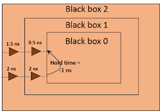
Hold time of the circuit is also dependent upon the reference point. For example, consider a multi-level black box as shown in figure 5. If we look at black box 0, its hold time is -1 ns. At level of black box 1, wherein clock travels 2 ns and data travels 0.5 ns to reach black box 0, hold time is (-1 + 2 - 0.5 = ) 0.5 ns. Similarly, at the level of black box 2, hold time is 1 ns. This is how, hold time depends upon the relative arrival times of clock and data. And it completely makes sense to have a negative hold time.
