Latchup and its prevention in CMOS devices

What is Latchup: Latchup refers to short circuit formed between power and ground rails in an IC leading to high current and damage to the IC. Speaking about CMOS transistors, latch up is the phenomenon of low impedance path between power rail and ground rail due to interaction between parasitic pnp and npn transistors. The structure formed by these resembles a Silicon Controlled rectifier (SCR, usually known as a thyristor, a PNPN device used in power electronics). These form a +ve feedback loop, short circuit the power rail and ground rail, which eventually causes excessive current, and can even permanently damage the device.
      
                                                                 
Latchup refers to short circuit formed between power rails in an IC leading to high current and damage to the IC. Speaking about CMOS transistors, latch up is the phenomenon of low impedance path in CMOS between power rail and ground rail due to interaction between parasitic pnp and npn transistors. The structure formed by these resembles a Silicon Controlled transistor (SCR, usually known as a thyristor, a PNPN device used in power electronics). These form a +ve feedback loop, short circuit the power rail and ground rail, which eventually causes excessive current and even permanently damage the device.
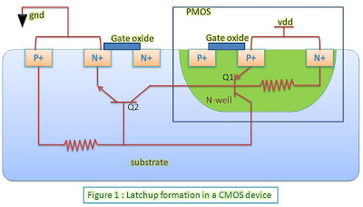
Figure 1: Latchup formation in CMOS
Latchup formation: Shown alongside is a CMOS transistor consisting of an NMOS and a PMOS device. Q1 and Q2 are parasitic transistor elements residing inside it. Q1 is double emitter pnp transistor whose base is formed by n well substrate of PMOS, two emitters are formed by source and drain terminal of PMOS and collector is formed by substrate(p type) of NMOS. The reverse is true for Q2. The two parasitic transistors form a positive feedback loop and is equivalent to an SCR (as stated earlier).

Analysis of latchup formation: Unless SCR is triggered by an external disturbance, the collector current of both transistors consists of reverse leakage current. But if collector current of one of BJT is temporarily increased by disturbance, resulting positive feedback loop causes current perturbation to be multiplied by β1β2 as explained below. The disturbance may be a spike of input voltage on an input or output pin, leading to junction breakdown, or ionizing radiations.

Because collector current of one transistor Q1 is fed as input base current to another transistor Q2, collector current  of Q2, Ic2 =  β2 * Ib2 and this collector current Ic2 is fed as input base current Ib1  to another transistor  Q1. In this way both transistors feedback each other and the collector current of each goes on multiplying.

Net gain of SCR device = β1 *β2

Total current in one loop = current perturbation * Gain

If     β1 *β2 >=1, both transistors will conduct a high saturation current even after the triggering perturbation is no longer available. This current will eventually becomes so large that it may damage the device.

Latch-up prevention techniques: Simply put, latchup prevention/protection includes putting a high resistance in the path so as to limit the current through supply and make β1 *β2 < 1. This can be done with the help of following techniques:

  • Surrounding PMOS and NMOS transistors with an insulating oxide layer (trench). This breaks parasitic SCR structure.
  • Latchup Protection Technology circuitry which shuts off the device when latchup is detected.
Read NextRegions of operation of MOS transistors

Metastability


What is metastability: Metastability is a phenomenon of unstable equilibrium in digital electronics in which the sequential element is not able to resolve the state of the input signal; hence, the output goes into unresolved state for an unbounded interval of time. Almost always, this happens when data transitions very close to active edge of the clock, hence, violating setup and hold requirements. Since, data makes transition close to active edge of clock, the flop is not able to capture the data completely. The flop starts to capture the data and output also starts to transition. But, before output has changed its state, the input is cut-off from the output as clock edge has arrived. The output is, then, left hanging between state ‘0’ and state ‘1’. Theoretically, the output may remain in this state for an indefinite period of time. But, given the time to settle down, the output will eventually settle to either its previous state or the new state. Thus, the effect of signal present at input of flop may not travel to the output of the flop partly or completely. In other words, we can say that when a flip-flop enters metastable state, one cannot predict its output voltage level after it exits the metastability state nor when the output will settle to some stable voltage level. The metastability failure is said to have occurred if the output has not resolved itself by the time it must be available for use. Also, since, the output remains in-between ‘0’ and ‘1’, which means both P-MOS and N-MOS are not switched off. Hence, VDD is shorted to GND terminal making it cause a high current to flow through as long as the output is hanging in-between.


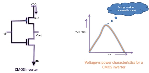
Metastability example: Consider a CMOS inverter circuit as shown below. The current vs voltage (we can also say power vs voltage as VDD is constant) characteristics for this circuit are also shown. It can be observed that output current is 0 for both input voltage levels; i.e. ‘0’ and ‘1’. As the voltage level is increased from ‘logic 0’, the current increases. It attains its maximum value at ‘Vin’ somewhere near VDD/2. It again starts decreasing as ‘Vin’ is increased further and again becomes 0 when ‘Vin’ is at ‘logic 1’. Thus, there is a local maxima for power consumption for CMOS inverter. At this point, the device is in unstable equilibrium. As for CMOS inverter, for other CMOS devices too, there lies ‘a local maxima’ at some value of input voltage. We all know that for a flip-flop, the output stage is a combinational gate (mostly an inverter). So, we can say that the output of the flip-flop is prone to metastability provided right input level.


Power characteristics of CMOS inverter
Figure 1: Power characteristics of CMOS inverter

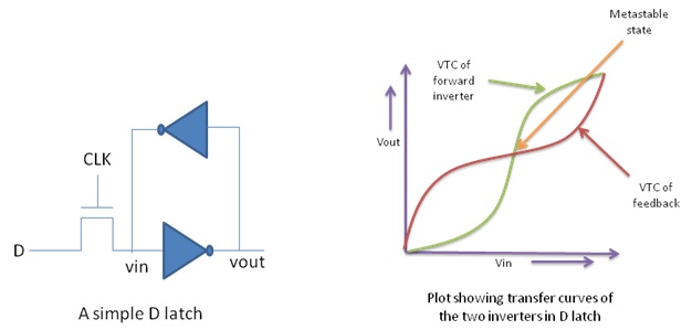
As we now know that a CMOS combinational gate has a point on its ‘voltage characteristic’ curve that is quasi-stable, let us look at a CMOS latch from the same perspective. The CMOS latch has a transmission gate followed by two inverters connected in feedback loop. The voltage characteristic curves for the two inverters are shown. The metastable point, here, lies where the two curves intersect as this point is the resulting peak point of the ‘Superposition curve’ resulting from the two individual curves. A latch goes into metastable state very frequently, especially if the input is changing fast. But, this metastability is resolved quickly as the output tends to go to one of its stable states. As a flop is generally made by connecting two latches in master-slave configuration, the flops are also prone to be metastable. The difference here is just that the probability of a flip-flop being metastable is a lot less than latches as ‘flops are edge sensitive’ as compared to latches which are level sensitive.


Figure showing transfer curve for D-latch and metastable point
Figure 2: Transfer curves of two inverters in a D-latch


We have just came to know that different elements are prone to metastability to different extents. There is a measure to determine the extent to which an element is prone to metastability failure. This is given by an interval known as ‘Mean Time Between Failures’ (MTBF) and is a measure of how prone an element is to failure. It gives the average time interval between two successive failures. The failure rate is given as the reciprocal of MTBF.