Setup and hold checks ensure that the finite state machine works in the way as designed. In essence, whole of the timing analysis, be it static or dynamic, revolves around setup and hold checks only. In this post, we will be touching upon setup and hold checks.
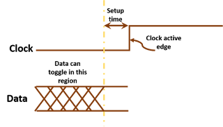
What is meant by setup check: Setup check ensures that the design transitions to the next state as desired through the state machine design. Mostly, the setup check is at next active clock edge relative to the edge at which data is launched. Let us call this as default setup check. This is, of course, in correspondence to state machine requirement to transfer to next state and the possibility of meeting both setup and hold checks together in view of delay variations accross timing corners. Figure 1 below shows the setup check for a timing path from positive edge-triggered register to negative edge-triggered register. It shows that the data launched by flop1 on positive edge will be captured by flop2 on the forthcoming negative edge and will update the state of flop2. To do so, it has to be stable at the input of flop2 before the negative edge at least setup time before.
What is meant by setup check: Setup check ensures that the design transitions to the next state as desired through the state machine design. Mostly, the setup check is at next active clock edge relative to the edge at which data is launched. Let us call this as default setup check. This is, of course, in correspondence to state machine requirement to transfer to next state and the possibility of meeting both setup and hold checks together in view of delay variations accross timing corners. Figure 1 below shows the setup check for a timing path from positive edge-triggered register to negative edge-triggered register. It shows that the data launched by flop1 on positive edge will be captured by flop2 on the forthcoming negative edge and will update the state of flop2. To do so, it has to be stable at the input of flop2 before the negative edge at least setup time before.
 |
| Figure 1: Default setup check for a timing path from positive edge-triggered to negative edge-triggered flop |
What is meant by hold check: Hold check ensures that the design does not move to the next state before its stipulated time; i.e., the design retains its present state only. The hold check should be one active edge prior to the one at which setup is checked unless there are some architectural care-abouts in the state machine design. The hold check corresponding to default setup check in such a scenario is termed as default hold check. Of course, there are some architectural care-abouts for this to happen. Figure 2 below shows the default hold check corresponding to the default setup check of figure 1. It shows that the data launched on positive edge by flop 1 should be captured by next negative edge and not the previous negative edge.
Default setup and hold check categories: As discussed above, for each kind of timing path, there is a default setup check and a default hold check that will be inferred unless there is an intended non-default check. We can split the setup and hold checks into following categories for our convenience. Each of the following is a link, which you can visit to know about the default setup and hold checks for each category:
Non-default setup and hold checks: These are formed when the state machine behavior is different than the default intended one. Sometimes, a state machine can be designed causing the setup and hold checks to be non-default. For this to happen, of course, you have to first analyze delay variations across timing corners and ensure that the setup timing equation and hold timing equation are satisfied for all timing corner scenarios. The non-default setup and hold checks can be modeled with the help of multi-cycle path timing constraints. You may wish to go through our posts Multicycle paths - the architectural perspective and Multicycle paths handling in STA to understand some of the concepts related to non-default setup and hold checks.
 |
| Figure 2: Default hold check for a timing path from positive edge-triggered |
Default setup and hold check categories: As discussed above, for each kind of timing path, there is a default setup check and a default hold check that will be inferred unless there is an intended non-default check. We can split the setup and hold checks into following categories for our convenience. Each of the following is a link, which you can visit to know about the default setup and hold checks for each category:
Non-default setup and hold checks: These are formed when the state machine behavior is different than the default intended one. Sometimes, a state machine can be designed causing the setup and hold checks to be non-default. For this to happen, of course, you have to first analyze delay variations across timing corners and ensure that the setup timing equation and hold timing equation are satisfied for all timing corner scenarios. The non-default setup and hold checks can be modeled with the help of multi-cycle path timing constraints. You may wish to go through our posts Multicycle paths - the architectural perspective and Multicycle paths handling in STA to understand some of the concepts related to non-default setup and hold checks.


